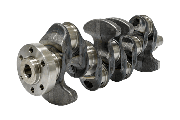
A thorough crankshaft inspection should be completed before an engine rebuild moves from teardown to parts ordering. The crankshaft is not just a heavy rotating component. Its main journals, crankpin journals, fillets, oil passages, flange, nose, keyways, and connection surfaces all affect how the rebuilt engine will run. A shaft that looks acceptable after cleaning may still have journal wear, taper, out-of-round, heat damage, surface cracking, or alignment problems that change the repair decision.
For heavy truck engine work, the purpose of crankshaft inspection is to create a documented condition record before anyone decides whether the shaft can be reused, machined, or replaced. That record should connect the crankshaft to the correct engine, preserve evidence from the bearings and lubrication system, show how the journals were measured, and separate visible findings from final serviceability decisions. This guide explains how to build that process without relying on generic limits that may not apply to the engine being repaired.
Why Crankshaft Inspection Should Start Before Cleaning
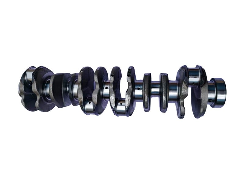
The first stage of crankshaft inspection begins as soon as the engine is dismantled. Before the crankshaft is washed, polished, or sent for machining, photograph the journals, fillets, oil holes, counterweights, flange, nose, keyways, and any visibly damaged areas. Keep the corresponding bearings in order so wear patterns can be compared with the journals that ran against them.
Heavy cleaning can remove deposits, discoloration, embedded debris, or transferred bearing material that may help explain what happened. The objective is not to preserve dirt; it is to preserve evidence long enough to record it. If one main bearing shows severe distress while the others look different, that pattern may matter later when the lubrication path, housing alignment, or local loading is reviewed.
A useful crankshaft inspection file therefore starts with “as removed” photographs and notes. Once those records exist, cleaning can proceed according to the appropriate workshop process.
Confirm Crankshaft Identity Before Measuring Anything
Before dimensional crankshaft inspection, confirm that the shaft belongs to the engine being rebuilt and record every available identifier. Useful evidence can include the full engine code, crankshaft reference, stamped or cast markings, previous repair records, and photographs of the front and rear connection ends.
This step is especially important when an engine has been rebuilt before. A crankshaft may have been replaced, reground, or installed from another version during an earlier repair. Do not assume that the component presently inside the engine is still the original production specification.
The current engine crankshaft product page similarly advises buyers to match the engine code, crankshaft reference, journal sizes, stroke, and connection ends before ordering. Those details should be treated as part of the identification process rather than as interchangeable clues.
Review Bearing Evidence During Crankshaft Inspection
Bearings can tell an important part of the story. A complete crankshaft inspection should therefore include the used main and connecting-rod bearings before they are discarded.
Look for wiping, scoring, embedded particles, fatigue, localized overheating, edge loading, unusual polishing, or differences between bearing positions. Record which shell came from which location. If a bearing has failed severely, photograph both the bearing and its corresponding journal.
The bearing pattern does not prove the root cause by itself. Similar-looking damage can result from contamination, oil starvation, insufficient clearance, misalignment, housing distortion, incorrect assembly, or other conditions. However, when bearing evidence is combined with journal measurements and oil-system findings, the crankshaft inspection becomes much more informative.
Clean the Crankshaft Without Destroying Inspection Evidence
After the initial condition is documented, the crankshaft can be cleaned so journal surfaces and oil passages can be examined properly. The cleaning method should suit the component material, contamination, and workshop process. Avoid methods that could create scratches, alter the surface, or hide defects that still need evaluation.
Pay particular attention to oil holes and cross-drillings. Debris trapped in an oil passage can remain after a bearing failure and later damage a rebuilt engine. If plugs are removed as part of the approved service procedure, document their original location and replacement requirements.
Once clean, repeat the visual crankshaft inspection under good lighting. Many fine scratches, heat marks, corrosion areas, and fillet defects are easier to see after oil residue and deposits are removed.
Inspect Main Journals and Crankpin Journals Visually
The running surfaces of the main journals and crankpin journals deserve close attention during crankshaft inspection. Look for scoring, scratches, pitting, corrosion, heat discoloration, smeared metal, unusual polishing, and visible ridges.
A journal can look smooth in a photograph while still having dimensional wear. Conversely, a light visible mark may not automatically make the crankshaft unusable. Visual condition and dimensional condition must be assessed separately.
| Observed Journal Condition | Possible Significance | Next Inspection Step |
|---|---|---|
| Light polishing | Normal contact or early wear may be present | Measure diameter, taper and out-of-round |
| Deep scoring | Debris or bearing distress may have damaged the surface | Measure damage depth and inspect oil system |
| Blue or dark heat marks | Local overheating may have occurred | Review bearing failure and assess material condition |
| Pitting or corrosion | Surface integrity may be compromised | Determine extent and whether machining is permissible |
| Transferred bearing material | Severe bearing contact may have occurred | Clean carefully and inspect underlying journal |
The purpose of this table is to organize the crankshaft inspection, not to create a universal pass/fail rule. Final acceptance should use the correct service information for the engine and the actual repair process.
Measure Journal Diameter at More Than One Position
A single micrometer reading is not enough for a meaningful crankshaft inspection. Journal diameter should be checked at the locations and orientations required by the applicable service procedure so taper and out-of-round can be evaluated.
For each journal, record the measuring point, instrument, reading, and orientation. If the shop measures at several axial positions and at perpendicular directions, keep those values in a table rather than reducing them immediately to one average number. The pattern may show localized wear that an average would hide.
Measurement quality matters because small differences can affect the repair decision. The NIST dimensional measurement resources explain the broader importance of controlled dimensional measurement and traceability. A rebuild workshop does not need laboratory conditions, but its crankshaft inspection should use suitable instruments and a repeatable method.
Check Journal Taper and Out of Round
Taper and out-of-round are two key dimensional findings in crankshaft inspection. Taper describes a change in diameter along the journal width, while out-of-round describes variation around the circumference. Both can affect oil-film behavior and bearing loading.
Do not use a generic internet value to decide whether the shaft is acceptable. The allowable limits depend on the engine, journal specification, bearing system, and repair procedure. The workshop should compare measured values with the correct service data.
If a journal has already been ground to a repair size, record that fact before ordering bearings or deciding on additional machining. A replacement bearing set must match the final journal size, not the nominal size of an unmachined crankshaft.
Inspect Fillets and Oil Hole Edges Carefully
Fillets around journal transitions and the edges of oil holes are critical areas during crankshaft inspection. These geometries can experience high local stresses, and damage introduced by poor grinding, sharp transitions, or surface defects may be more important than a cosmetic mark on a low-stress surface.
Inspect fillets under good lighting and magnification appropriate to the workshop process. Look for visible cracking, grinding marks, nicks, corrosion, or damage near the journal transition. Oil-hole edges should also be checked for burrs, damage, or abnormal wear.
ASTM maintains specific standards for magnetic particle examination of crankshaft forgings. Its current A986/A986M specification divides continuous-grain-flow crankshaft forgings into inspection zones and identifies crankpin journals, main bearing journals, oil holes, and fillet areas as important inspection regions. That standard is not a universal service limit for every truck crankshaft, but it illustrates why critical areas should not be treated the same as the rest of the shaft.
Use Non Destructive Testing When the Repair Requires It
Visual crankshaft inspection cannot reveal every surface or near-surface defect. Where the crankshaft material, repair procedure, or failure history makes crack detection necessary, an appropriate non-destructive testing method may be used by qualified personnel.
Magnetic particle inspection is widely used for ferromagnetic components and can be appropriate for certain crankshaft forgings. However, the inspection procedure, magnetization technique, surface condition, interpretation, and acceptance criteria must match the applicable standard or approved repair specification.
ASTM A456/A456M covers magnetic particle examination of certain large forged steel crankshafts, while A986/A986M addresses continuous-grain-flow crankshaft forgings for specified applications. These documents demonstrate that crack examination is structured around material, crankshaft type, inspection zone, and acceptance criteria. They should not be used to invent a pass/fail rule for an unrelated engine.
Check Crankshaft Straightness and Runout
A complete crankshaft inspection may also require checking straightness or runout, particularly after a major bearing failure, overheating event, impact, or suspected distortion. The exact setup and allowable value must come from the applicable engine or repair documentation.
The measurement should be made on appropriate support points with a suitable indicator and controlled setup. Record where the indicator was positioned and how the shaft was supported. If the setup changes, readings may not be directly comparable.
A runout reading outside the applicable limit does not automatically mean the same repair action for every crankshaft. Some shafts may have an approved correction or machining route, while others may require replacement. The crankshaft inspection should document the measurement first and apply the correct repair standard second.
Inspect the Crankshaft Nose and Front Drive Features
The front end of the crankshaft is often overlooked when journal wear dominates the teardown discussion. During crankshaft inspection, examine the nose, keyways, threads, gear seats, pulley or damper interfaces, and any drive surfaces.
Look for fretting, damaged threads, enlarged keyways, impact marks, corrosion, or wear on fitted surfaces. A crankshaft with acceptable journals may still create assembly problems if a front connection has been damaged.
When a replacement crankshaft is being sourced, photograph these interfaces clearly. Two crankshafts with similar journal layouts can still differ at the front drive or accessory connection.
Inspect the Rear Flange and Flywheel Interface
The rear flange is another essential part of crankshaft inspection. Check the flywheel mounting face, bolt holes or threads, pilot features, seal running surface, and any visible signs of fretting or distortion.
Oil leakage at the rear of an engine should not automatically be blamed on the crankshaft, but the seal running area should be examined for grooves or damage. If a repair sleeve or previous modification is present, record it.
For replacement purchasing, the rear flange configuration and connection details should be part of the fitment package. This is particularly useful when the crankshaft reference is unclear or when the engine has a previous repair history.
Review Oil Passages and Lubrication Evidence
A crankshaft can pass dimensional crankshaft inspection while the engine still has a lubrication problem that will damage the rebuild. Oil passages, bearing shells, oil pump condition, filter history, contamination, and previous low-pressure symptoms should be reviewed together.
If a bearing has failed, inspect the crankshaft drillings for debris. Cleaning only the visible journal surface is not enough if particles remain in the internal oil circuit. The workshop should use the approved cleaning and verification process for the particular crankshaft.
If the engine had low oil pressure before teardown, review the earlier low oil pressure diagnostic guide. The existence of journal damage does not automatically prove that the oil pump was the root cause.
Compare All Main Journals and Crankpins as a Set
One of the advantages of structured crankshaft inspection is that patterns become visible across the entire shaft. Do not review each journal in isolation and discard the relationship between them.
If only one journal shows severe damage, investigate what was unique about that position. If several journals show similar wear, look for system-wide causes such as contamination, lubrication problems, incorrect clearances, or alignment issues. If damage progresses from one end of the shaft to the other, preserve that pattern in the inspection notes.
A comparison table that lists journal number, measured diameters, visible condition, bearing condition, and comments can be more useful than a narrative description alone.
Build a Crankshaft Inspection Record Before Machining
Before the crankshaft is sent for grinding, polishing, or another repair process, create a baseline crankshaft inspection record. This protects the workshop from losing the original condition evidence and helps the machine shop understand the requested work.
| Inspection Item | Record Before Machining | Reason |
|---|---|---|
| Engine identity | Engine code, crankshaft reference, photos | Confirms application |
| Main journals | Diameter readings, taper, out-of-round, surface notes | Defines wear condition |
| Crankpins | Diameter readings and surface condition | Supports bearing and machining decisions |
| Fillets and oil holes | Visual findings and any NDT results | Captures critical-area condition |
| Runout | Measured result and setup description | Documents shaft alignment condition |
| Front and rear interfaces | Photos and damage notes | Supports fitment and assembly review |
| Repair history | Known previous grinding or repair size | Prevents incorrect bearing selection |
This record should travel with the machining request where practical. The final post-machining dimensions can then be compared against the original crankshaft inspection rather than existing as an isolated set of numbers.
Decide Between Reuse, Machining and Replacement
The final purpose of crankshaft inspection is to support a repair decision. That decision should consider journal size, surface condition, available repair sizes, crack-test results where required, runout, fillet integrity, connection damage, previous machining history, and the engine manufacturer’s limits.
Reuse may be possible when the shaft remains within the correct specification and the surfaces are acceptable. Machining may be appropriate when an approved repair size or process exists. Replacement may be required when defects, dimensional condition, previous machining, or interface damage place the shaft outside an approved repair path.
No single photograph or measurement should be used as a universal decision rule. The serviceability decision belongs to the engine-specific repair specification and qualified technical review.
What to Send When Requesting a Replacement Crankshaft
If the crankshaft inspection shows that replacement is required, the purchasing request should carry forward the same evidence used during teardown. Send the complete engine code, crankshaft reference, clear photographs of markings, journal information, front and rear connection details, and required quantity.
If the old shaft has been reground previously, state the known repair size. If the reference is unclear, send the physical interface photographs rather than guessing. The product listing for the engine crankshaft specifically recommends confirming journal sizes, stroke, and connection ends as part of application review.
For a direct matching review, use the contact page and send the engine code, part reference, interface photos, and relevant inspection findings. The purpose is to match the replacement shaft to the actual engine configuration, not simply to a general engine family.
How Crankshaft Inspection Protects the Rest of the Rebuild
A disciplined crankshaft inspection does more than decide the fate of one component. It affects bearing selection, oil-clearance planning, connecting-rod work, block alignment checks, lubrication-system cleaning, and the final parts order.
If the inspection reveals contamination, the rebuild plan should address the contamination source. If journal wear is uneven, housing alignment or rod condition may need review. If the shaft has already been machined, the correct bearing size must be selected. If cracking is suspected, appropriate non-destructive testing may be required before further work.
This is why crankshaft evaluation should happen early in the rebuild sequence. Ordering bearings, rods, or related parts before the final shaft condition is known can force purchasing changes later.
Conclusion
A reliable crankshaft inspection combines identification, visual evidence, dimensional measurement, critical-area examination, alignment checks, and repair history. It begins before cleaning, continues through measurement and any required non-destructive testing, and ends only when the workshop has enough evidence to decide whether the crankshaft can be reused, machined, or replaced.
The most important rule is to avoid generic assumptions. Journal limits, runout values, repair sizes, and acceptance criteria must come from the correct engine and repair documentation. By preserving the evidence and recording measurements systematically, a workshop can make a stronger rebuild decision and prepare a much clearer replacement inquiry if a new crankshaft is required.
FAQ
What should be included in a crankshaft inspection?
A complete crankshaft inspection should include component identification, visual examination of journals and critical areas, journal measurements, taper and out-of-round checks, runout or straightness checks when required, oil-passage review, front and rear interface inspection, and crack testing when the repair procedure calls for it.
Can a crankshaft be reused if the journals look smooth?
Visual appearance alone is not enough. A smooth journal can still have excessive wear, taper, out-of-round, or an unsuitable repair size. Measure the journals and compare the results with the applicable engine specification before deciding on reuse.
When is magnetic particle inspection used on a crankshaft?
Magnetic particle inspection may be used on suitable ferromagnetic crankshafts when the repair procedure or failure history requires examination for surface or near-surface discontinuities. The method, inspection zones, and acceptance criteria must match the applicable material and technical standard.
Should crankshaft runout be checked during every rebuild?
The applicable engine service procedure should determine when runout or straightness measurement is required. It is particularly relevant after severe bearing damage, overheating, impact, or suspected distortion, but the measuring setup and limit must be engine-specific.
What information is needed when ordering a replacement crankshaft?
Send the engine code, crankshaft reference, journal information, stroke where required, clear photographs of markings, front and rear connection details, known previous repair size, and required quantity. A good crankshaft inspection record provides most of this information.